METAL DETECTORS
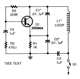
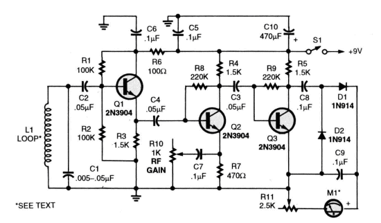
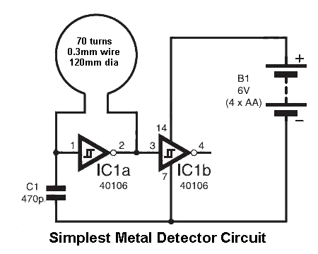
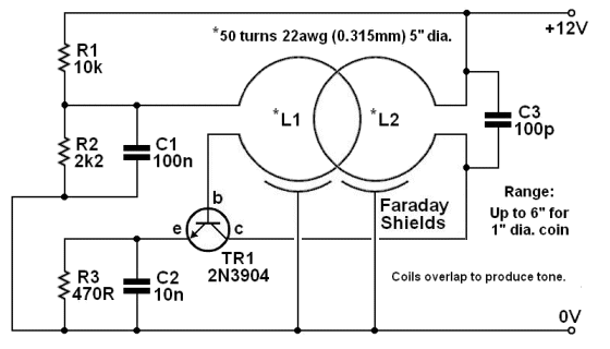
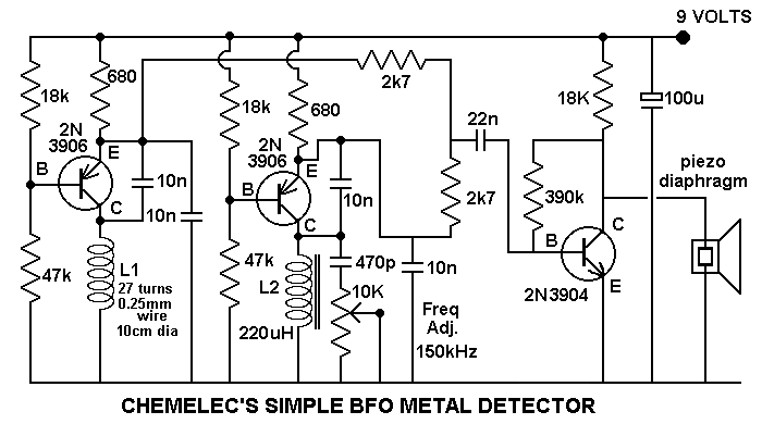
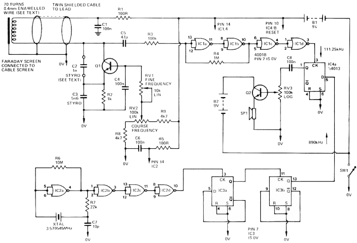
Links to more pages on Metal Detectors: Remember this: almost all circuits (up to about 4 - 6 transistors) have the same capability: detecting a 20mm coin at about 100mm. It doesn't matter if the circuit is simple or complex, The sensitivity revolves around the circuit driving the coil. Some circuits are more sensitive to "interference" and we have demonstrated this in Circuits 1 - 8 at the end of the page. The most-sensitive circuit is a 100mm dia coil with just 12 to 20 turns and operates at about 200kHz as shown in circuit 8. The frequency of the circuit will change by one Hertz and this can be detected on an AM radio. You cannot get better than this. When a metallic object disturbs the magnetic field of the search coil, the frequency of the search oscillator shifts slightly and the detector will produce a signal in the audio frequency range. Although once popular, BFO's are no longer being made by professional metal detector manufacturers. They are simple and inexpensive, but do not offer the accuracy and control of modern PI or VLF detectors. Attempts have been made to add new features such as discrimination and more advanced models were produced in the 1970s, but they were soon replaced by recent, more sophisticated technology. BFO designs are still used in cheap hand-held devices and in low quality, toy type detectors. The Simplest Metal Detector Circuit is also shown below and it only requires 4 components. The detector is a modified balanced scale, which indicates ferrous objects and magnetized items. A magnet is attached to one end of the arm and a simple north/south scale is attached at the opposite end. A pivot is located near the magnet end of the arm and a slide balancing weight is on the opposite end.
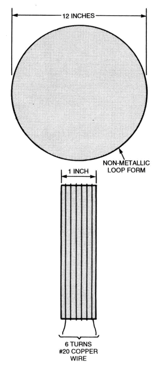
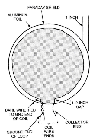
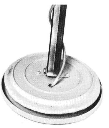
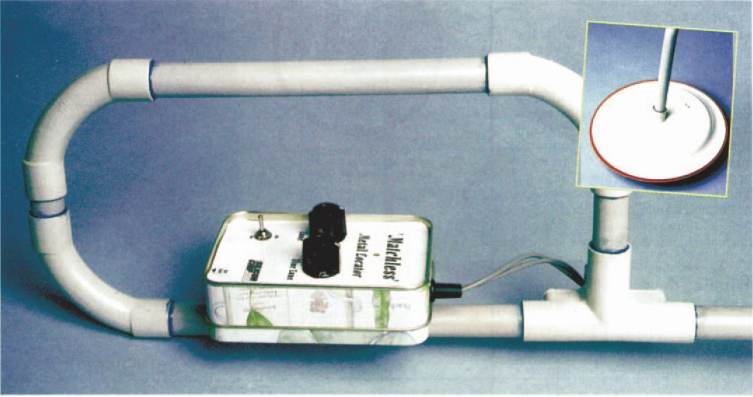
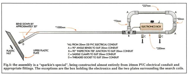
Fig. 3. This detailed diagram of the loop shows the leads
Building The Loop Building The Receiver The simplest metal detector circuit consists of 4 components.
Note that these figures may not apply in the ground, where depth of penetration will depend largely on the mineralisation present.
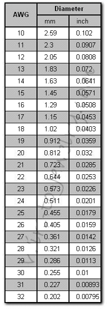
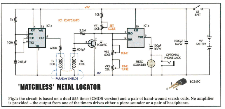
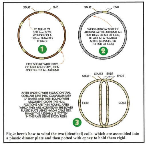
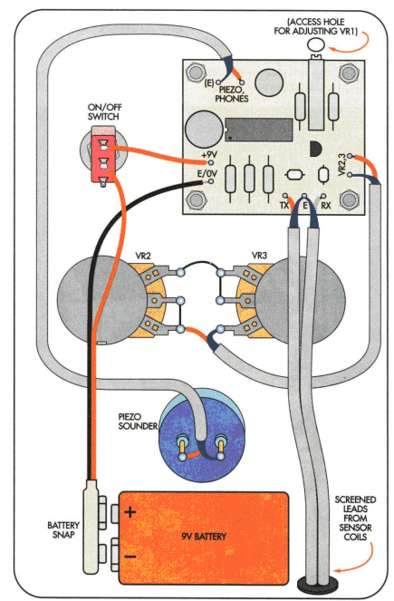
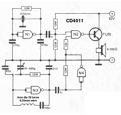
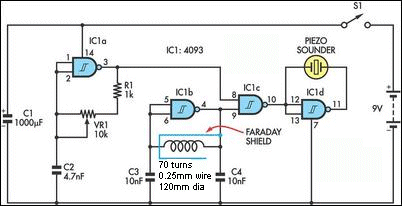
The receiver section (IC1b) is preceded by a simple yet sensitive preamplifier stage, based on Q1, which amplifies the signal received from the Rx coil. This is fed directly to IC1b, which is used here as a high-performance sine-square converter. Its input at pins 8 and 12 is biased by the divider formed by the 10k resistor and pots VR1-VR3, so that only pulses of a certain amplitude break through to output pin 9. Here is a Metal Detector using a CD4011 IC: The metal detector’s coil is made of: 70 turns of enamelled copper with dia. 0.25mm on a 5cm dia former.
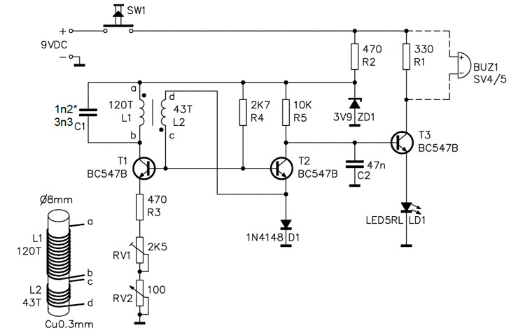
Another Simple Metal Detector Circuit:
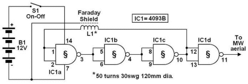
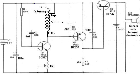
Another Simple Metal Detector Circuit: SIMPLE METAL DETECTOR USING A TAPPED COIL CD 4093 IC Metal Detector
This circuit uses a single coil and nine components to make a particularly OP AMP METAL DETECTOR
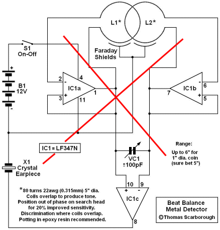
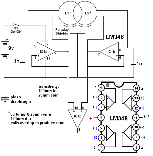
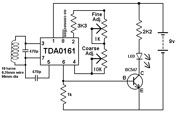
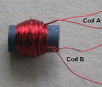
The circuit above did not work with LM 348 and it was modified as shown below to work with LM348. The circuit above works very well and only uses 4 components and two coils. It is the simplest self-contained circuit and the Simple Oscillator / Pipe Locator TDA 0161 METAL DETECTOR IC
This IC is useless. It is expensive and performs very poorly. It will detect a small coin at 10mm.
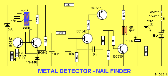
Nail Finder
Kits for Metal Detector kit - Nail Finder $17.00 plus postage
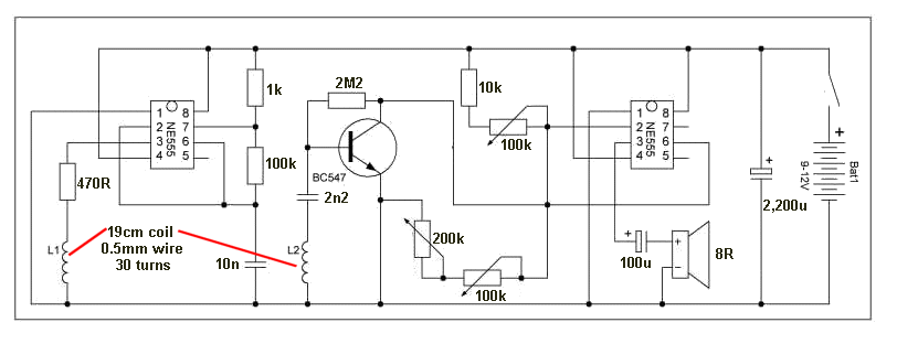
555 METAL DETECTOR
Here is a discussion on how a number of oscillators work and the surprising | |||
| METAL DETECTOR OSCILLATORS Generally, an oscillator is designed to produce a STABLE OUTPUT. We don't want an oscillator to drift - change frequency - but for Metal Detection, we want the oscillator to be sensitive to outside influence. This makes it very SENSITIVE. These oscillators have the coil exposed to the surroundings and the turns have a very large diameter. This type of oscillator is used to detect the presence of a metal object. The metal will alter the inductance of the coil by absorbing some of the magnetic flux and increase or decrease the frequency of the circuit, depending on the type of metal. There are two types of metal - as far as magnetism is concerned. Magnetic and non-magnetic. But when an oscillating magnetic field is present, another feature is present. All metals that conduct electricity will produce eddy currents when exposed to an oscillating magnetic field and this will absorb some of the magnetic flux. This will increase the inductance of the coil and reduce the frequency. Most of the oscillator circuits are Colpitts and can consist of 5 to more than 15 components. The whole idea of the circuit is to make it stable when "sitting around" but allow the slightest magnetic influence to change the frequency. This is called the SENSITIVITY of the circuit and we will be providing a number of circuits for you to test and compare their sensitivity. These circuits operate between 100kHz and 500kHz and to detect when they shift by as little as 1Hz, we use a stable reference oscillator. The oscillator is an AM radio. It has an inbuilt 455kHz oscillator and when placed near a Metal Detecting Oscillator, it picks up the signal, (just like a radio station) and produces a whistle. This whistle represents the difference in frequency of the two oscillators. It is called a BEAT-FREQUENCY or Difference Frequency. By tuning across the band you will get a lowering in frequency until the whistle stops. At this point the two oscillators are the same frequency or one is a multiple of the other and the difference produces a zero- frequency beat. If a coin is brought near the detecting coil, the change in frequency will be heard. Even though this arrangement is very simple, it is equal to all the BFO (Beat Frequency Oscillator) Gold detectors on the market. |
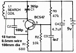
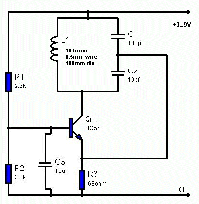
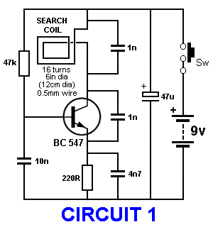 | The circuit is a Colpitts Oscillator and is placed near an AM radio to produce a whistle. The circuit operates at about 500kHz. The radio is tuned so the whistle is reduced to zero. When a metal object is placed near the coil, the frequency of the transmitter is reduced and a whistle is heard in the radio. Compare this circuit will the others to determine the most sensitive circuit. Note: 4n7 between collector and emitter (in place of the 1n) produces a better signal - easier to find on AM radio. The thickness of the wire makes very very very little difference. But the number of turns and the diameter of the coil makes a very BIG difference to the actual frequency at which the circuit will oscillator. In this circuit the frequency of operation does not matter as it will only change the position on the dial. |
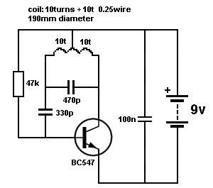
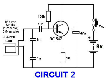 This circuit is a good performer. Current 4mA. Easy to find signal on AM radio. The circuit operates at about 1MHz and the beat-frequency can be found on the dial at 1,000kHz. | In this circuit the coil is not driven directly but receives a very small amount of energy from the feedback provided by the signal on the emitter of the transistor. The coil and the two 1n capacitors (in series) produce a TUNED CIRCUIT and will produce natural oscillations. The transistor sees this and produces the same waveform on the emitter but with a greater amount of "strength." This "strength" is not needed by the Tank Circuit but it needs a signal and the signal from the emitter is sufficient to maintain oscillation. |
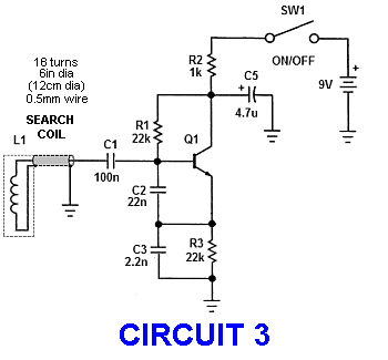 | By keeping the size of the search coil nearly the same in all circuits, we can determine if the arrangement of the components improves the sensitivity. Circuits 2 and 3 are SHUNT-FED Colpitts Oscillators. In a Shunt-fed oscillator, DC is not passed through the Tank or Oscillator section. |
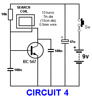 | This is a very simple circuit produced by a reader. See if it works. Circuit does not work with 10k. Reduce 10k to 3k3 and circuit keeps changing frequency. Very hard to find on AM radio. |
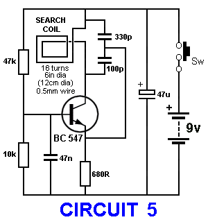 | This circuit is the same as circuit 1 but the TUNING CAPACITOR across the coil is tapped and the tapping (feedback) is passed to the emitter. |
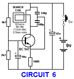 | This circuit is the same as circuit 5 but the emitter resistor is reduced and the transistor takes more current. See if this improves the sensitivity. |
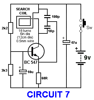 | Every component in this circuit is the wrong value. Build the circuit and see if it works. |
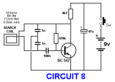 This circuit is the best performer. Current 2mA. Easy to find the signal on AM radio. The circuit operates at about 1MHz and the beat-frequency can be found on the dial at 1,000kHz. The circuit is very similar to #2 but this time the feedback signal from the collector has a larger amplitude and the voltage across the coil is about 15v p-p. This produces a very clean and clear signal on an AM radio and is the best performer of all the circuits. The Tank Circuit operates in a very unusual way. The tapping (between the two capacitors) is connected to 0v and does not move. When the magnetic flux in the coil collapses, it charges both 1n capacitors in series and although it does not charge both equally, the bottom terminal of the coil drops downwards easily because the base-emitter junction of the transistor is seeing a reverse-voltage and does not offer any opposition. This turns the transistor OFF and the top 1n starts to charge via the 4k7 resistor. The top terminal of the coil rises due to the charging of the top 1n and as the voltage produced by the coil reduces, the voltage on both ends of the 100n starts to rise and turn ON the transistor. The voltage across the base-emitter junction cannot rise above 0.7v, so the transistor turning ON will remove the voltage across the top 1n Changing the 100n "pick-off" to 10n makes no difference so the value of this capacitor is not important. It simply connects the tank circuit to the transistor and does not affect the timing of the circuit. |
| METAL DETECTOR OSCILLATORS - CONCLUSION The best circuit is #8 where the Tank Circuit (the self-oscillating circuit - the coil and capacitors) will produce a good waveform (large amplitude) that is easy to pick-up on an AM radio at about 1,000kHz. Don't forget, this circuit is a special type of oscillator that is stable in operation but is easily "upset" by the change inductance of the coil. This means the Tank Circuit has to be lightly loaded and although it is connected to the base via a 100n capacitor, the transistor is providing a feedback signal that is compensating for the losses delivered to the base. The emitter waveform was measured on a CRO as 15v p-p for 9v supply. The transistor is a common-emitter amplifier and the circuit is a SHUNT-FED Colpitts Oscillator because no DC is passed through the Tank (oscillator) section. These 8 circuits are a perfect example for an experiment to show you cannot predict how a circuit will work and which circuit will perform the best. No simulation-software package will show the enormous difference between the circuits. That's why you have to build EVERYTHING and OBSERVE the results yourself. The secret to getting a TANK CIRCUIT (more-accurately . . . a RESONANT CIRCUIT) to produce a good sinewave is shown in circuit 8. The reason why a Resonant Circuit will produce a voltage up to twice rail-voltage is due to the fact that the inductor produces a voltage in the reverse direction when it collapses. |
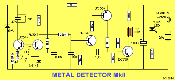
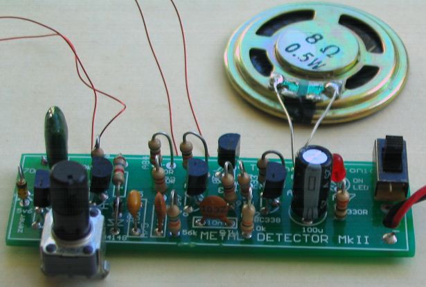
| FINAL DESIGN FOR A METAL DETECTOR We now want to produce the simplest and BEST metal detector. We will be using a microcontroller to take the signal from the detecting circuit and analyse the waveform to produce a beep when meal is detected. If you look at all the Metal Detector circuits, you will find the complexity of the circuit revolves around detecting the small change in frequency or amplitude of the detecting circuit. This can take as many as 8 to 15 chips in the older circuits as each chip only performs very small task. When using a microcontroller, all this can be done with an 8-pin device and the program does all the work We have two choices for the detecting circuit. The Metal Detector MkII front-end changes amplitude when metal is detected and the remainder of the circuit amplifies this change and produces a tone. Circuit 8 produces a change in frequency. If we want to detect the first sign of change-in-frequency, we need to have two oscillator operating at exactly the same frequency and detect the difference. Alternatively you need to count the cycles for one second and detect the change. This means a reading will take 1 second to get a result. Alternatively you can use the Metal Detector MkII circuit and detect the immediate change in output voltage. However this circuit has a "sweet spot" and needs to be constantly re-adjusted to produce the point where it is sensitive to "interference." This adjustment is difficult to do with a microcontroller. The first three transistors of the Metal Detector MkII circuit will produce a change is about 1mV and this can be detected by the Analogue channel in the microcontroller - providing the circuit can be automatically adjusted. All Metal Detector circuits have been designed along the wrong lines. They have a fixed reference oscillator and detect the change in frequency of the scanning coil. But the frequency of this coil is changing all the time due to natural drift in the oscillator and the setting of the Metal Detector has to be constantly re-adjusted so the output is zero and no tone is produced by the speaker when nothing is being detected. It is much more clever to adjust the reference oscillator on a constant basis and thereby produce silence when not detecting and when something is detected, the two oscillators will differ by a small amount. But our clever design goes further. When you sweep over a nugget of gold and then sweep back again, TWO HIGH-LOW PULSES are produced within 3 seconds. This is what the microcontroller detects and interprets as a "sample." In this way we have eliminated 95% of all false triggering. It is surprising no-one has thought of this concept before. The final design is in the process of being developed. 6-1-2018 |
| Answers: 1. The PCB coil does not concentrate the flux and only a few of the turns are being affected fully by the presence of the piece of magnetic material and the other turns are being effect less and less (as they are further from the object being detected). 2. The base-emitter junction across the coil puts a load on the coil and reduces the amplitude to about 1200mV. 3. The single turn feedback winding only delivers 1:50 of the change in output of the coil. When designing a project, you don't know what WILL work but we have explained what will NOT WORK. We have covered some of the features of BAD design. The operation of the "pick-up head" is much more complex than meets the eye. |


