Cell Phone Signal Jammer using 555 Timer IC– In this tutorial, you will learn how to make your own low-cost Cell Phone Signal Jammer using the NE555 Timer IC and some other electronic components. This is only for educational purposes and that’s the reason this Cell Phone Signal Jammer has a small range.
Before you start building this project make sure you have the basic knowledge about the 555 Timer IC, Transistors, Capacitors, and Resistors.
Components needed for the Cell Phone Signal Jammer:
NE555 Timer IC
BF495 Transistor
2PF Ceramic Capacitor
4.7PF Ceramic Capacitor
3.3PF Ceramic Capacitor
47PF Ceramic Capacitor
30PF Variable / Trimmer Capacitor
1uF 63V Electrolytic Capacitor
10K Resistor
6.8K Resistor
82K Resistor
220E Resistor
5.6K Resistor
24 AWG Copper Wire
3 Pin Mini Slide Switch (SPDT)
3mm LED (Green)
2Pin Male Header Connector
9V Battery Connector
9V Battery
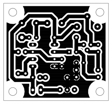
Cell Phone Signal Jammer PCB board:
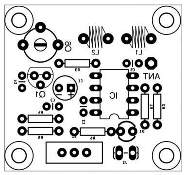
Components Placement “Silkscreen”:
Cell Phone Jammer Making:
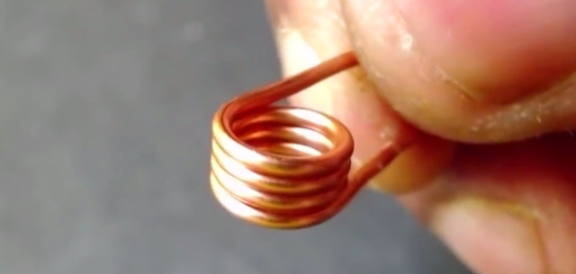
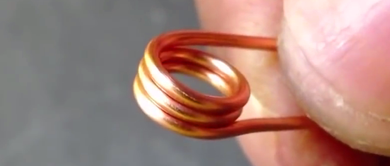
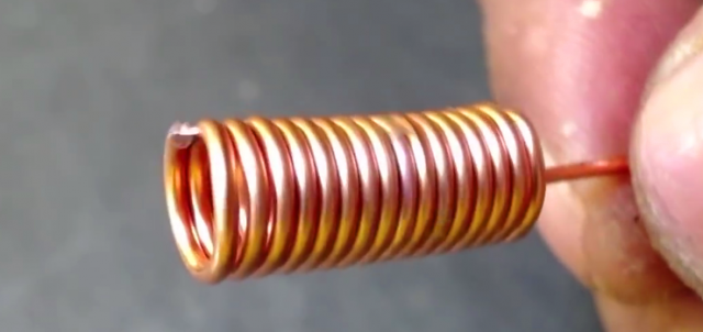
First Coil- 4 turns 5mm of 24 AWG wire. I used a screw driver of making this coil.
Second Coil- 3 turns 5mm of 24 AWG wire.
Third Coil- 15 turns 5mm of 24 AWG wire.
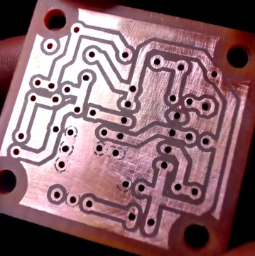
Cell phone Jammer PCB board:
For the PCB design transferring, Etching, and Drilling watch my video tutorial.
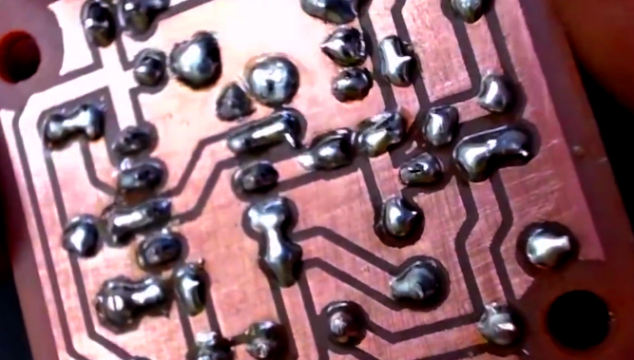
After fixing all the electronic components, finally, I completed the soldering. I doubled checked all my connections using a digital Multimeter, and luckily there were no solder bridges.




No comments:
Post a Comment